

ASME SA789 UNS S32205 Duplex Stainless Steel U-Tubes
Nov 16, 2026
Leave a message
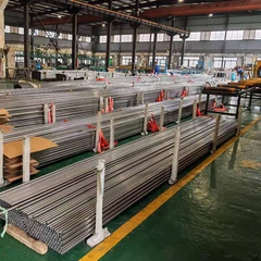
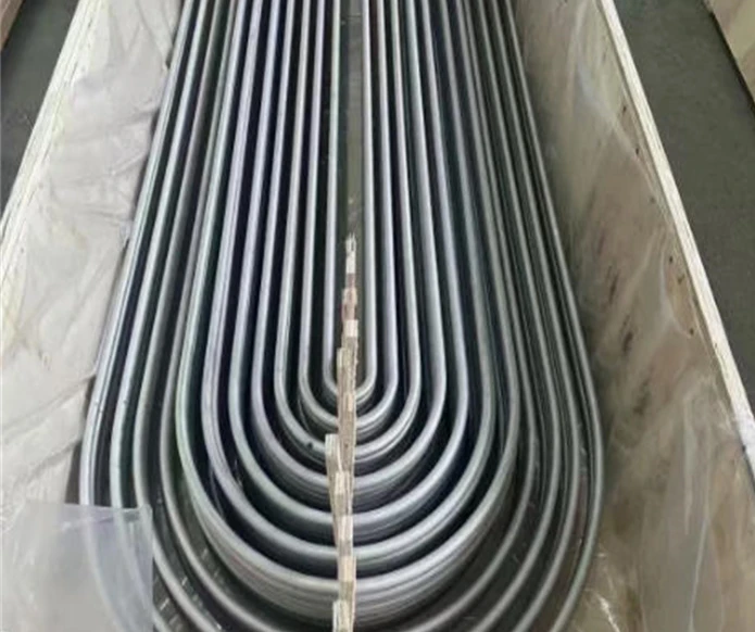
Are you looking for reliable U-tube bundles for shell-and-tube heat exchangers operating in high-chloride environments, sour (H₂S-containing) service, or seawater cooling systems? We supply ASME SA-789 / ASTM A789 UNS S32205 Duplex Stainless Steel U-Tubes, with strict control over bending processes, post-bending heat treatment and microstructure to help ensure long-term service performance.
We have over 18 years of experience in special alloy manufacturing, with products exported to more than 60 countries. We have successfully supplied over 80 projects involving heat exchangers, seawater desalination and the oil and gas industries. Typical applications include seawater cooling heat exchangers, refinery sour-water condensers, heat-recovery exchangers in desalination plants, chemical brine coolers and offshore platform process heat exchangers.
UNS S32205 duplex stainless steel features a balanced ferrite-austenite microstructure, typically containing approximately 50% of each phase. With a Pitting Resistance Equivalent Number (PREN) of ≥34 and yield strength nearly twice that of 316L austenitic stainless steel, it offers superior performance to 316L in many brackish-water, seawater cooling, process brine and refinery sour-water cooling applications.
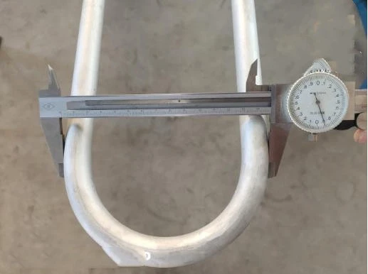
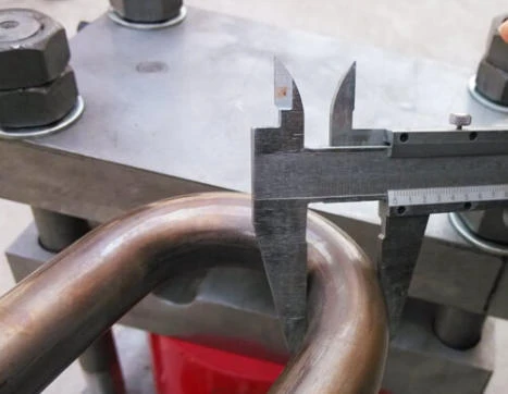
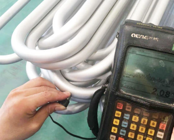
We strictly follow minimum bending-radius requirements (typically ≥1.5 times the tube outside diameter) and apply targeted heat treatment to the bend area and 300 mm extensions on both sides. This helps minimize residual stress while avoiding harmful intermetallic phase formation. Wall thinning is controlled to within 10% of the nominal wall thickness, and every U-tube undergoes comprehensive dimensional inspection.
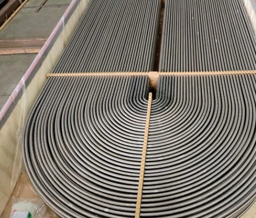
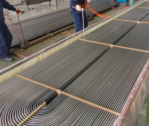
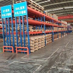
We can supply ASME A789 UNS S32205 U-Tubes with outside diameters ranging from 12.7 mm to 50.8 mm and wall thicknesses from 1.2 mm to 3.0 mm. Customized U-tube lengths, bending radii and tube spacing are available according to your heat exchanger bundle design. The standard lead time for custom U-bending orders is 28–40 working days. Delivery can be faster when existing straight-tube stock is available for processing. All U-tubes are fitted with end-protection caps, separated by soft protective materials and packed in seaworthy wooden cases to prevent scratches and deformation during transportation.
ASME SA-789 UNS S32205 Duplex Stainless Steel U-Tubes Specification
|
Parameter |
Specification |
|---|---|
|
Standard |
ASME SA-789 / SA-789M (ASTM A789 / A789M); General Requirements: ASME SA-1016 / ASTM A1016M |
|
U-Bend Standard |
TEMA Standards (Class R, C or B) / ASME Section VIII, Division 1 / Customer Drawings |
|
Grade / Alloy |
UNS S32205 / Duplex 2205 / EN 1.4462; Dual-certified to UNS S31803 upon request |
|
Manufacturing Process |
Seamless (Cold-Drawn / Cold-Pilgered) or Welded (Autogenous Welding, Bead-Rolled and Solution-Annealed) |
|
Supply Condition |
Solution-Annealed and Pickled or Bright-Annealed; U-Bent (As-Bent or Post-Bend Solution-Annealed) |
|
Outside Diameter (OD) |
12.7–50.8 mm (1/2"–2"); Common sizes: 15.88, 19.05, 25.4 and 31.75 mm |
|
Wall Thickness |
1.24–3.40 mm (BWG 18–BWG 10); Minimum Wall or Average Wall |
|
Straight Leg Length |
Up to 15,000 mm; Straight tube length before bending can reach approximately 30 m |
|
Bending Radius (R) |
Minimum 1.5 × OD; Up to 1,500 mm, subject to TEMA requirements and tube-sheet layout |
ASME SA-789 / ASTM A789 UNS S32205: Chemical Composition
|
Element |
Chemical Composition (%) |
|---|---|
|
Carbon (C) |
0.030 max |
|
Manganese (Mn) |
2.00 max |
|
Phosphorus (P) |
0.030 max |
|
Sulfur (S) |
0.020 max |
|
Silicon (Si) |
1.00 max |
|
Nickel (Ni) |
4.5–6.5 |
|
Chromium (Cr) |
22.0–23.0 |
|
Molybdenum (Mo) |
3.0–3.5 |
|
Nitrogen (N) |
0.14–0.20 |
|
Iron (Fe) |
Balance |
|
PREN |
≥ 34 (Typical: 34.5–36.5) |
PREN = Cr + 3.3 × Mo + 16 × N.
ASME SA-789 / ASTM A789 Mechanical Properties
solution-annealed condition at room temperature:
|
Mechanical Property |
UNS S32205 Requirement |
|---|---|
|
Tensile Strength, min. |
655 MPa (95 ksi) |
|
Yield Strength (0.2% Offset), min. |
450 MPa (65 ksi) |
|
Elongation in 2 in. (50 mm), min. |
25% |
|
Hardness, max. |
293 HBW / 31 HRC |
|
Ferrite Content |
40–60% |
|
Microstructure |
Duplex ferrite-austenite structure |
|
Ferrite Measurement Method |
ASTM E562 (where specified) |
Heat Treatment Requirements
|
Process Stage |
Requirement |
|---|---|
|
Straight Tube Solution Annealing |
Heat to 1020–1100°C (1870–2010°F), followed by rapid cooling in water or air, as permitted by the applicable specification and manufacturing procedure, to achieve the required duplex phase balance and minimize intermetallic precipitation. |
|
U-Bend Condition |
Supplied as-bent when permitted by design requirements, or post-bend solution-annealed according to the approved procedure. |
|
Post-Bend Solution Annealing |
U-bend and at least 150 mm (6 in.) of straight tangent sections heated to 1020–1100°C using controlled resistance or induction heating, followed by rapid cooling. Inert gas protection may be applied as required. |
|
Heat Treatment Precaution |
Avoid uncontrolled exposure to 450–900°C, which can promote sigma-phase precipitation. Prolonged exposure near 475°C can also cause embrittlement. |
Dimensional and U-Bend Tolerances
Straight Tube Tolerances
|
Parameter |
Tolerance / Requirement |
|---|---|
|
Outside Diameter (OD) |
±0.10–±0.20 mm, depending on OD and applicable SA-1016 tolerance table |
|
Minimum Wall Thickness (OD ≤ 1-1/2 in.) |
+20% / -0% |
|
Minimum Wall Thickness (OD > 1-1/2 in.) |
+22% / -0% |
|
Average Wall Thickness |
±10% |
U-Bend Tolerances
|
U-Bend Parameter |
Standard Tolerance / Requirement |
|---|---|
|
Bend Radius (R) / Center-to-Center Distance (2R), 2R ≤ 600 mm |
±1.6 mm (±1/16 in.) |
|
Bend Radius (R) / Center-to-Center Distance (2R), 2R > 600 mm |
±3.2 mm (±1/8 in.) |
|
Leg Length (L) |
+3.2 mm / -0 mm (+1/8 in. / -0 in.) |
|
Squareness of Cut Ends |
Within 0.5 mm |
|
Wall Thinning at Extrados |
Minimum remaining wall thickness must meet the specified design requirement; typical thinning target ≤15–18%, subject to verification |
|
Ovality at Bend |
8–10% maximum, subject to agreed specification or TEMA requirements |
|
Flatness / Coplanarity |
Bent legs must lie in a single plane within ±1.6 mm |
Testing & Inspection
| Test / Inspection Item | Standard / Method | Scope & Requirement |
| Chemical Analysis | ASTM E1473 / OES | Heat and product analysis |
| Mechanical Tests | SA-789 / SA-1016 | Tension Test, Flattening Test, Reverse Flattening Test (welded), Flaring/Flange Test, Rockwell/Brinell Hardness Test |
| Straight Tube NDE / Hydro | SA-1016 | 100% Hydrostatic Test or Nondestructive Electric Test (Eddy Current / Ultrasonic) |
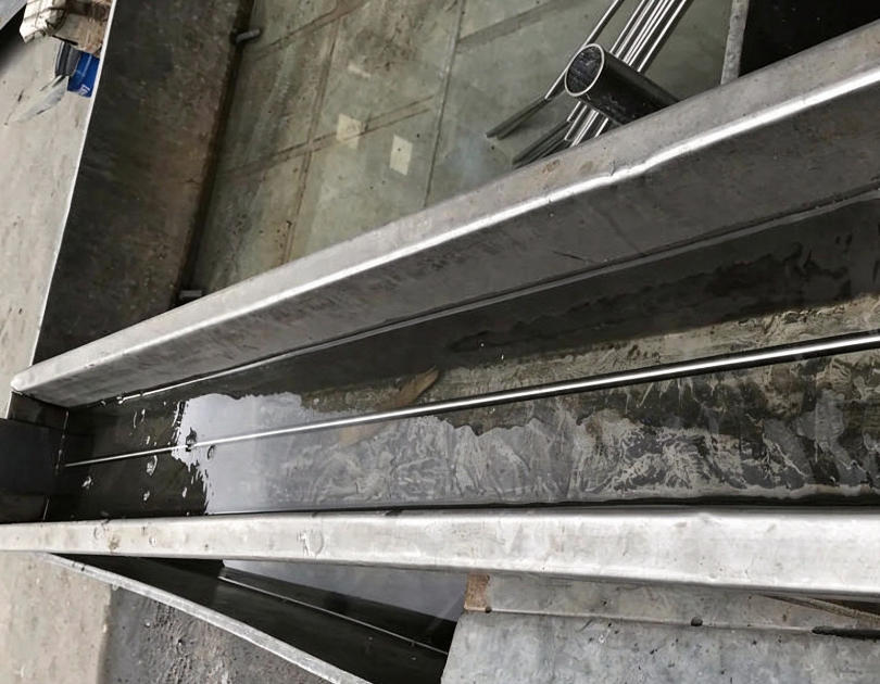
| Post-Bend Hydrostatic / Air Test | TEMA / Customer Spec | 100% of finished U-tubes hydrostatically tested (and/or Air-Under-Water pneumatic leak tested) after bending |
| Liquid Penetrant Testing (PT) | ASTM E165 | 100% PT on the U-bend extrados/intrados and 150 mm tangents (especially for tight bend radii or annealed bends) |
| Detrimental Intermetallic Phase (Optional/Spec) | ASTM A923 (Methods A, B, C) | Method A (Microstructure etch), Method B (Charpy Impact, wall thickness permitting), Method C (Ferric Chloride pitting test at 25 °C) |
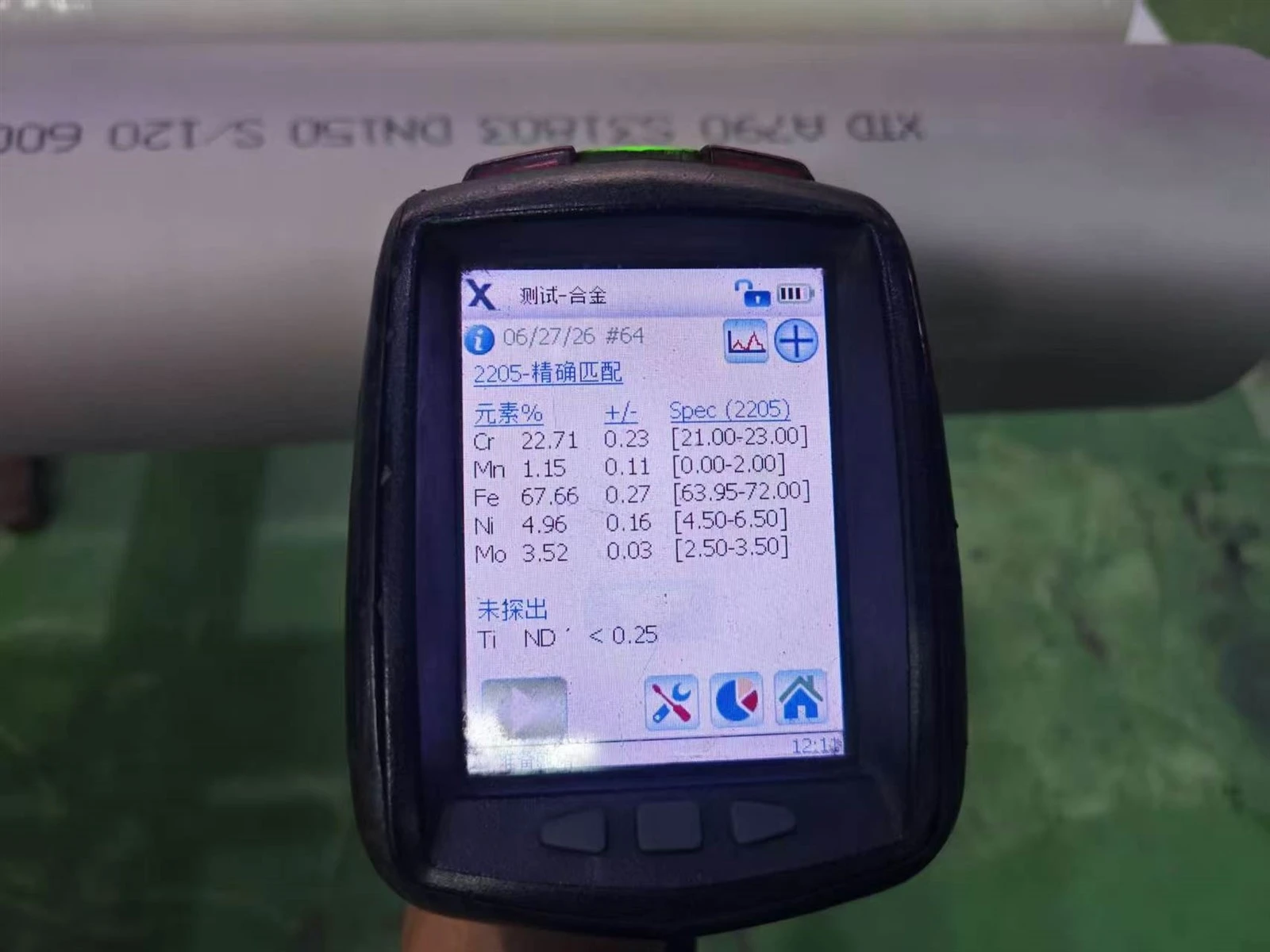
| Ferrite Content & PMI (Optional) | ASTM E562 / Feritscope / XRF | 40%–60% Ferrite verification; 100% PMI |
Marking, Packaging & Certification
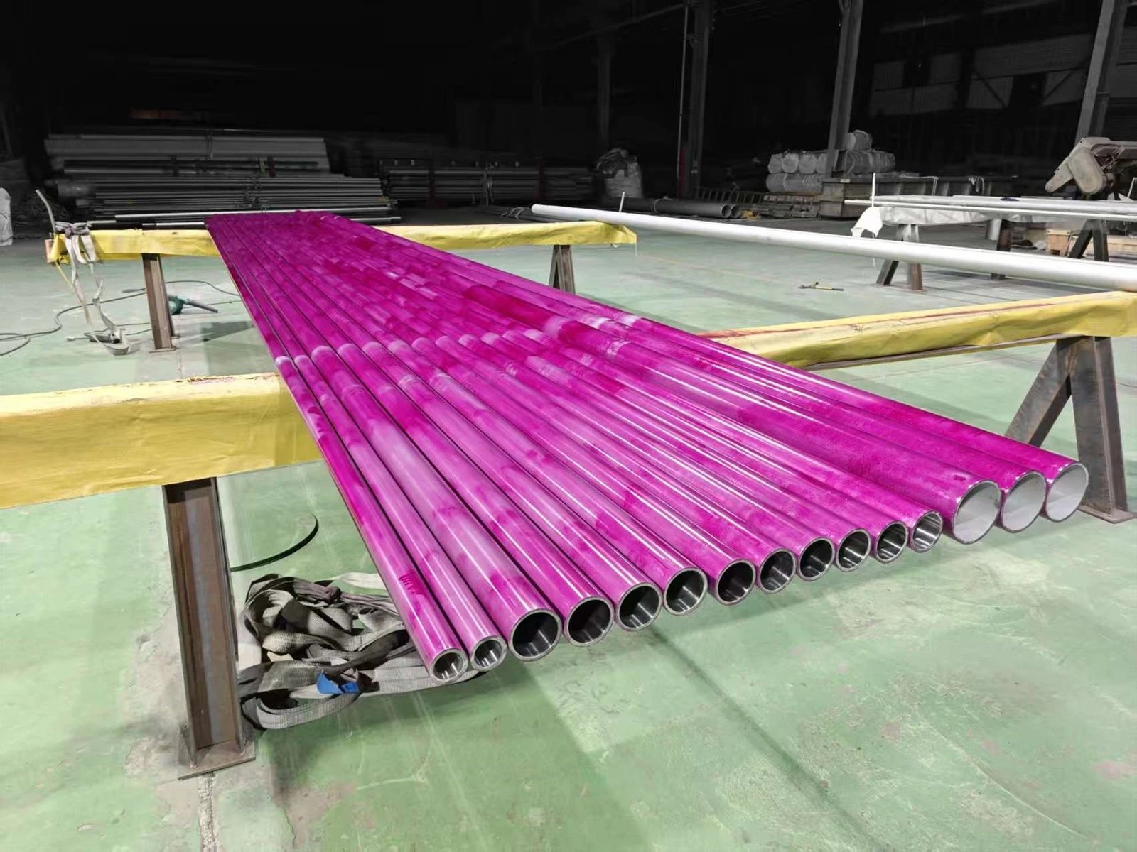
Marking: Ink-jet or electro-etched along straight legs with Manufacturer Logo, ASME SA-789, UNS S32205, SMLS/WLD, OD × WT, Heat Number, Bend Radius/Row No., and Hydro/NDE mark.
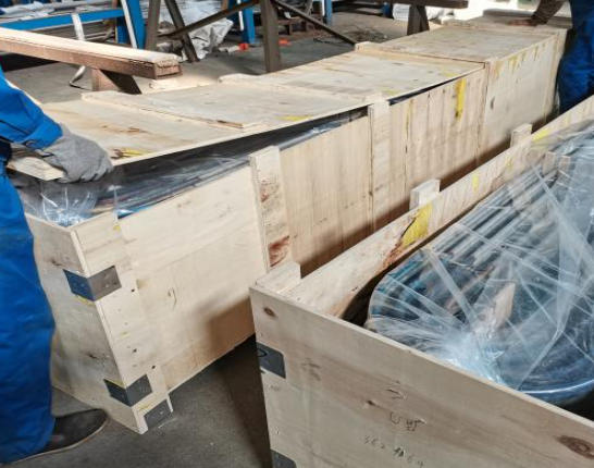
Packaging: Ends capped; U-tubes bundled and layered by bend radius with protective cardboard/foam separators, securely braced inside heavy-duty seaworthy wooden cases (fumigated/plywood) to prevent leg distortion during transit.
Certification: Mill Test Certificate (MTC) per EN 10204 3.1 (including chemical, mechanical, straight/post-bend heat treatment records, NDE/hydro reports, and optional ASTM A923 report).
Send Inquiry