

Welding Stainless Steel Foil: Processes, Parameters and Quality Control
Feb 20, 2025
Leave a message
Stainless steel foil is a demanding welding proposition. Where sheet welding tolerates small variations in current and travel speed, foil of 0.05 to 0.2 mm thickness can burn through or fail to fuse inside a window of a few amperes. Reliable production therefore depends on three things: selecting a low-heat-input process, controlling joint fit-up and heat sinking, and qualifying every thickness and joint combination before serial production. This guide sets out the processes that work on foil, the starting parameters to develop from, and the cleaning and inspection steps that keep thin-gauge assemblies leak-tight and corrosion resistant.
What Counts as Stainless Steel Foil
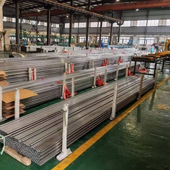
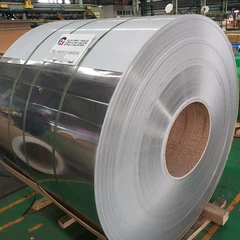
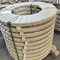
Foil is generally defined as flat-rolled stainless steel below 0.2 mm in thickness, supplied in widths from a few millimetres up to roughly 600 mm, in coils, spools or cut lengths. The thin section changes the welding physics: heat is conducted away much faster than in sheet, the molten pool has almost no stiffness, and surface tension rather than gravity holds the weld together. Distortion and buckling appear at very low heat input, so clamping and backing design matter as much as the process choice.
Common foil grades follow the same standards as sheet product:
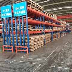
304 and 304L to ASTM A240 or EN 1.4301 / EN 1.4307 for general purpose and mildly corrosive service.
316L to ASTM A240 or EN 1.4404 where chloride-bearing media, marine atmosphere or process chemicals are present.
321 and 347 stabilised grades for service temperatures that would otherwise sensitise unstabilised austenitic foil.
430 ferritic foil to ASTM A240 for decorative, magnetic or heat-transfer duties.
JIS G4304 / JIS G4305 is used when the drawing calls out SUS designations.
Tolerances, surface finish and edge condition should be agreed to ASTM A480 or EN 10088-2, because camber and burr height directly affect weld gap control.
Welding Processes Suitable for Foil
The processes normally used on foil are all low-energy, high-stability variants of arc, beam and resistance welding. Covered electrode and conventional metal inert gas welding, which are often listed in general stainless welding guidance, are unsuitable here: the arc force and slag of covered electrode welding need about 1.5 to 2 mm of section, and even short-arc gas metal arc welding struggles below roughly 0.8 mm.
| Process | Practical foil range | Strengths | Main limitations |
|---|---|---|---|
| Pulsed micro-TIG (GTAW) | 0.05 - 0.5 mm | Stable arc at low current, good bead appearance, works autogenously or with 0.4 - 0.8 mm filler wire | Needs precise arc length control and a pulsed power source |
| Micro-plasma arc welding (PAW) | 0.10 - 1.0 mm | Concentrated, very stable arc with excellent penetration control | Higher equipment cost, nozzle and electrode consumables |
| Laser beam welding (LBW) | 0.05 - 1.0 mm | Lowest heat input, high speed, narrow heat affected zone, minimal distortion | Tight gap tolerance, high capital cost, reflective surface needs care |
| Resistance seam and spot welding | 0.03 - 0.5 mm | No filler, very fast, ideal for lap joints and foil-to-foil joining | Lap joints only, electrode wear, surface marking |
| Electron beam welding (EBW) | 0.10 - 1.0 mm | Deep narrow weld with very small heat effect | Vacuum chamber limits part size |
For most production work the choice reduces to pulsed micro-TIG for short runs and mixed joint types, laser or resistance seam welding for continuous high-volume strip, and micro-plasma where penetration consistency across a varying gap must be guaranteed.
Joint Design, Fit-Up and Backing
Foil joints are almost always square butt or lap configurations, and preparation quality decides whether the process works at all:
Square butt joints with no bevel. Target a gap of 0.05 mm or less for laser welding and 0.1 mm or less for micro-TIG.
Lap joints for resistance welding with an overlap of three to five times the foil thickness.
Deburr sheared edges and remove slivers; a burr or a rolled edge creates a thick-to-thin transition that either fails to fuse or burns back.
Copper or aluminium backing bars with a shallow grooved channel under the joint to conduct heat away and support the pool.
Hold-down fingers or clamp bars placed within 2 to 3 mm of the weld line to stop buckling ahead of the arc.
Tack welds at 5 to 15 mm pitch using reduced current, then close the seam in one continuous pass where possible to avoid stop-start defects.
A mismatch of even 10 per cent of thickness across the joint is significant in foil, so incoming coil should be checked for thickness variation and crown before welding fixtures are finalised.
Welding Parameters and Shielding Gas
The table below gives typical starting ranges for fully austenitic foil in the annealed condition. They are development points for procedure qualification, not fixed settings: every combination of grade, thickness and joint type has to be proven by test.
| Foil thickness | Process | Peak / pulse current | Travel speed | Shielding gas |
|---|---|---|---|---|
| 0.05 - 0.08 mm | Pulsed micro-TIG | 2 - 8 A | 150 - 300 mm/min | Argon 99.99 %, 6 - 10 L/min |
| 0.08 - 0.15 mm | Micro-TIG or micro-plasma | 6 - 18 A | 200 - 400 mm/min | Argon 99.99 %, 8 - 12 L/min |
| 0.15 - 0.20 mm | Micro-plasma or laser | 15 - 30 A or 100 - 300 W | 300 - 600 mm/min | Argon 99.99 % |
| 0.20 - 0.50 mm | TIG or laser | 25 - 60 A or 300 - 800 W | 400 - 900 mm/min | Argon 99.99 % |
Points that decide weld quality more than any single number:
Gas purity. Pure argon is the standard choice and purity directly controls bead colour. Use 99.99 % or better; moisture and oxygen in the supply produce grey or black oxide.
Backing and trailing gas. Purge the underside at 5 to 10 L/min and add a trailing shield for laser and plasma welding so the hot bead does not oxidise behind the torch.
Pulsing. Pulse frequencies from a few hertz to a few hundred hertz with 30 to 50 per cent duty let the weld cool between pulses, which limits distortion and grain growth.
Electrode. A 1.0 to 1.6 mm ceriated tungsten electrode ground to a 20 to 30 degree taper gives a stable low-current arc.
Pre-flow and post-flow. Roughly 0.5 to 1 second pre-flow and 3 to 5 seconds post-flow protect the start and crater.
Filler metal. Autogenous welding suits thin foil; where extra reinforcement is needed, use 0.4 to 0.8 mm matching filler such as ER308L or ER316L, and keep travel speed high enough to melt the wire without raising current.
Cleaning, Passivation and Inspection
Foil welds are judged as much on cleanliness as on geometry. Weld discolouration is a chromium-depleted oxide that reduces corrosion resistance, and any free iron left on the surface will rust even on 316L.
Degrease with acetone or an alkaline cleaner and dry before welding; oil and moisture cause porosity and arc wander.
Remove heat tint after welding by pickling paste, electrolytic weld cleaning or mechanical finishing, then rinse thoroughly.
Passivate the cleaned surface to rebuild the chromium oxide film. Chemical passivation follows ASTM A967, with cleaning and descaling practice per ASTM A380.
Use dedicated stainless steel brushes, files and grinding wheels. Carbon steel tooling transfers free iron that appears later as rust spots.
Visual inspection: a light straw tint on thin foil is generally acceptable, while grey, blue-black or sooty deposits indicate excessive heat input or shielding loss.
Leak testing by immersion bubble test or helium mass spectrometry for sealing applications, plus weld cross-section examination on first-off samples.
Intergranular corrosion testing to ASTM A262 where sensitisation is a risk; low-carbon or stabilised grades reduce that risk in the first place.
Procedure qualification to ISO 15614-1 or ASME Boiler and Pressure Vessel Code Section IX, and welder qualification to EN ISO 9606-1 or ASME Section IX, should be in place before series production.
Frequently Asked Questions
Q: Can stainless steel foil be welded without filler wire?
Yes. Square butt joints in foil down to about 0.05 mm are normally welded autogenously with micro-TIG, plasma or laser processes. Filler is only added when the joint cannot be fitted closely enough or when extra reinforcement is required, and it should be a matching 0.4 to 0.8 mm wire.
Q: Which welding process gives the best result on stainless steel foil?
There is no single answer. Pulsed micro-TIG is the most flexible for mixed joints and short runs, laser welding gives the lowest distortion at high speed, micro-plasma handles inconsistent gaps well, and resistance seam welding is the fastest route for lap joints in long strip.
Q: Why does the weld on foil turn blue or black?
Colour is an oxide film formed when the hot metal is exposed to oxygen. Blue or black usually means the shielding gas flow, purity or trailing coverage is inadequate, or heat input is too high. Remove the tint by pickling and restore passivity afterwards.
Q: What is the thinnest stainless steel foil that can be welded?
Resistance seam and spot welding is practical down to roughly 0.03 mm, while arc and laser processes become difficult below about 0.05 mm because the pool has almost no stiffness and burn-through risk rises sharply.
Q: Should 304 or 316L foil be used for welded assemblies?
Choose 316L when chlorides, marine atmosphere or process chemicals are present, because its molybdenum content raises pitting resistance. Use 304 or 304L for general and mildly corrosive service. Low-carbon grades are preferred wherever a welded joint will see elevated service temperature.
Q: Does welding make stainless steel foil magnetic?
Annealed austenitic foil is essentially non-magnetic, but cold work and, to a lesser extent, weld solidification can introduce light magnetism. This is normal for 304 and 316L and does not by itself indicate a defect, although strong ferromagnetism may point to a wrong grade.
Send Inquiry